How to use ARC board
Purpose
- To get familiar with the usage of ARC board and on-board peripherals
- To know how to program and debug the ARC board and on-board peripherals
Requirements
The following hardware and tools are required:
- PC host
- GNU Toolchain for ARC Processors / MetaWare Development Toolkit
- ARC board (EM Starter Kit / IoT Development Kit)
embarc_osp/arc_labs/labs/lab5_emsk/embarc_osp/arc_labs/labs/lab5_iotdk
Content
- A brief introduction of ARC board and on-board peripherals
- Based on embARC OSP, program the GPIO to control some on-board peripherals
Note
About the detailed usage of embARC OSP, see How to use embARC OSP
Principles
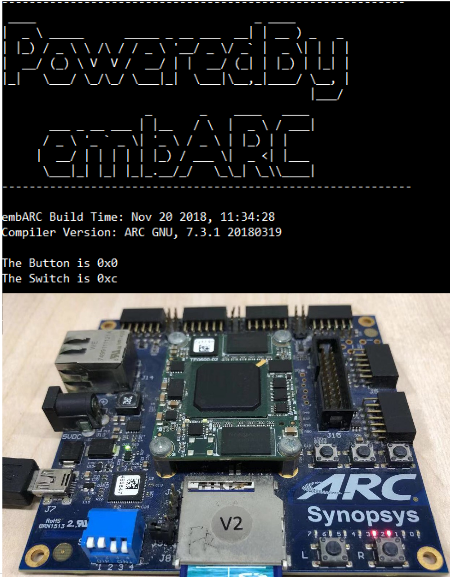
EM Starter Kit
About the brief introduction of EM Starter Kit, see to embARC OSP Documentation
There are LEDs, DIP switches, and buttons on EM Starter Kit, this lab shows
how to program the GPIO to control these on-board peripherals of EM Starter Kit.
The code for this lab is located in embarc_osp/arc_labs/labs/lab5_emsk. In the code, the on-board buttons and DIP switches’ values
are read, and whether LEDs are on or off depend on the value of the buttons and DIP switches.
IoT Development Kit
About the brief introduction of IoT Development Kit, see embARC OSP Documentation
As there are no LED or other easy-to-use peripherals on IoT Development Kit, this lab shows how to control a LED through the arduino interface of IoT Development Kit.
The code for this lab is located in embarc_osp/arc_labs/labs/lab5_iotdk. In the code, the external connected LED blinks periodically.
Steps
EM Starter Kit
- Connect EM Starter Kit to your computer, select em7d configuration and open UART terminal.
- Compile and run the
embarc_osp/arc_labs/lab5_emskexample with the following commands:
cd /arc_labs/lab5_emsk
make BOARD=emsk BD_VER=22 CUR_CORE=arcem7d TOOLCHAIN=gnu run
- Press the buttons (L or/and R) and toggle the DIP switches (3 or/and 4), then check the result in UART terminal, and watch the changes of on-board LEDs.
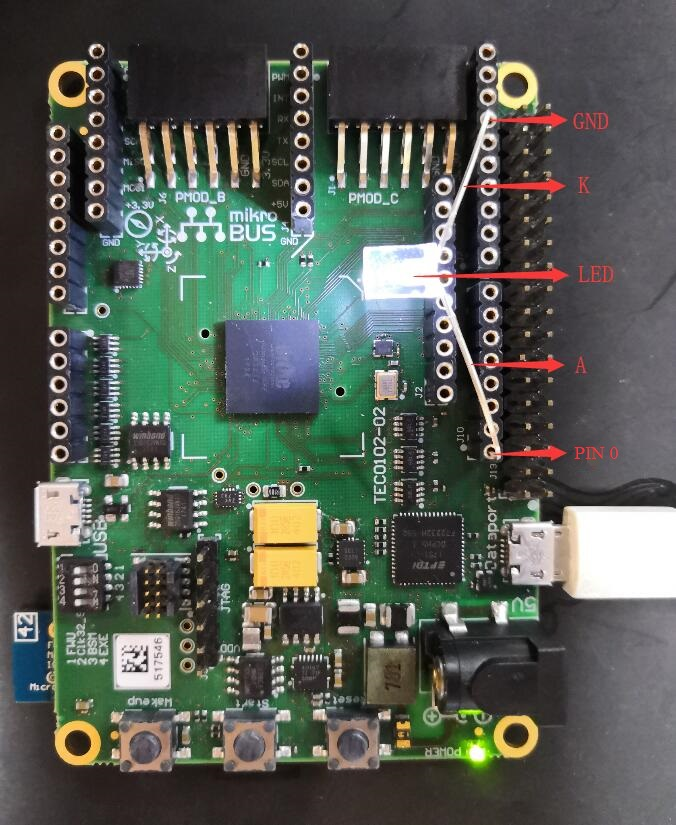
IoT Development Kit
IoT Development Kit has an arduino interface, here select arduino digital pinout ARDUINO_PIN_0(iotdk gpio4b_2[0]) to control LED.
- Find a LED, connect the LED anode pin to ARDUINO_PIN_0, connect the LED cathode pin to GND of IoT Development Kit.
- Connect the USB cable to the USB data port of IoT Development Kit and the computer.
- Compile and run the
embarc_osp/arc_labs/lab5_iotdkexample with the following commands:
cd /arc_labs/lab5_iotdk
make BOARD=iotdk TOOLCHAIN=gnu run
- Watch the changes of external connected LED.
Note
The connection between LED and IoT Development Kit is just for test. A 1kΩ resistor should be added in series connection to limited the current and prevent damage to I/O pin.
Exercises
Try to create you own application to control the peripherals of ARC board
Note
The ARC IoT Development Kit is powered over USB. Note that the ARC IoT Development Kit needs to be powered by an external power adapter if additional devices are connected to the extension interfaces. External power supply must be 5V DC (A 12V power supply will most probably damage your board).