A simple bootloader
Purpose
- Understand the memory map of ARC boards
- Understand the principles of bootloader and self-booting
- Understand the usage of shell commands in cmd
- Create a self-booting application
Requirements
The following hardware and tools are required:
- PC host
- GNU Toolchain for ARC Processors / MetaWare Development Toolkit
- ARC board (EM Starter Kit / IoT Development Kit)
- SD card
example/baremetal/bootloader
Simple Bootloader
This simple bootloader is designed to work as a secondary/simple bootloader
for embARC OSP, it loads boot.hex or boot.bin on SD Card and run that program.
The example can be used as ntshell application.
The following features are provided in this simple bootloader:
- Boot application from SD card
- File operations on SD card
- UART Y-modem protocol to update application
- Operations on ARC processors
Content
- Build and run the
example/baremetal/bootloader - Download the generated
bootloader.bininto flash - Build a self-boot application and boot it from SD card
- Use the ntshell commands
Principles
Memory Map of ARC board
EM Starter Kit
The available memory regions of EM Starter Kit are shown below:
| Name | Start address | Size |
|---|---|---|
| on-chip ICCM | 0x00000000 | 256/128 KB |
| on-chip DCCM | 0x80000000 | 128 KB |
| on-board DDR RAM | 0x10000000 | 128 MB |
In this lab, the last 1 MB of DDR (starting from 0x17f00000) is reserved for the simple bootloader, other memory regions are available for application.
IoT Development Kit
The available memory regions of IoT Development Kit are shown in the following table:
| Name | Start address | Size |
|---|---|---|
| on-chip eflash | 0x00000000 | 256 KB |
| external boot SPI flash | 0x10000000 | 2 MB |
| on-chip ICCM | 0x20000000 | 256 KB |
| on-chip SRAM | 0x30000000 | 128 KB |
| on-chip DCCM | 0x80000000 | 128 KB |
| on-chip XCCM | 0xC0000000 | 32 KB |
| on-chip YCCM | 0xE0000000 | 32 KB |
In this lab, on-chip eflash and on-chip SRAM are reserved for the simple bootloader, CCMs are reserved for application.
Boot of ARC board
EM Starter Kit
The EM Starter Kit uses a Xilinx SPARTAN-6 FPGA part which can be configured to run different members of the ARCv2 EM Processor family. The EMSK includes a SPI flash pre-programmed with four FPGA configurations of ARC EM cores.
When a “power on” or reset/configure is issued, the FPGA auto-loads one of the pre-installed FPGA configurations from SPI flash. After the FPGA configuration is loaded from the SPI flash, a simple primary bootloader is loaded in ICCM. Through the primary bootloader, an application can be loaded from SPI Flash into ICCM or external DDR memory.
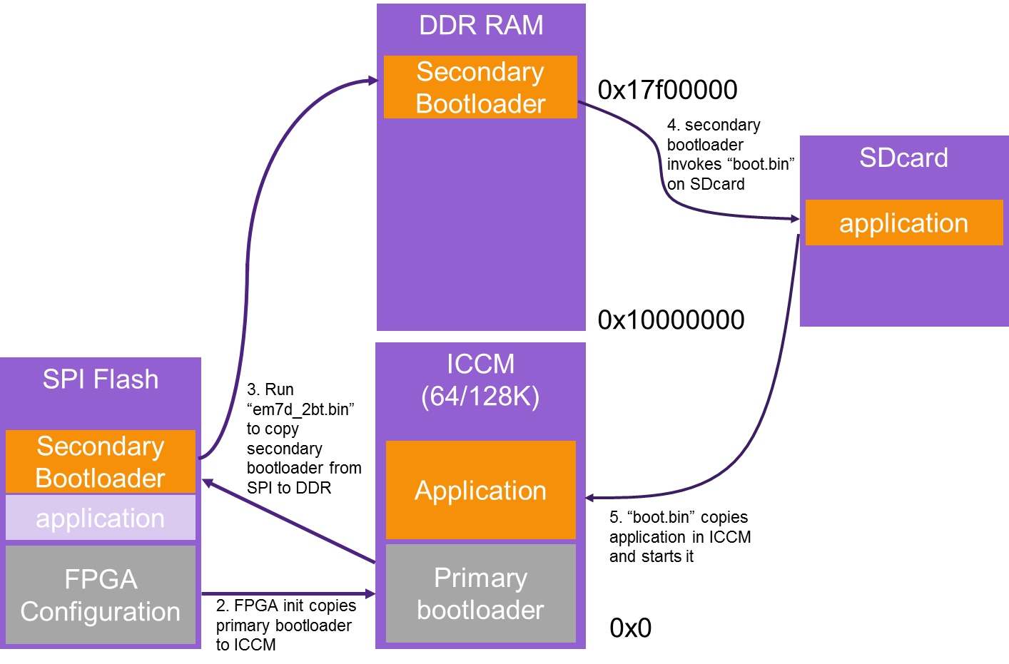
Considering that the SPI Flash is used to store FPGA images, the secondary bootloader is designed based on the primary bootloader to load an application from an SD card since it can be read and written easily. The startup sequence is listed below:
- Power on or reset event.
- Load FPGA configuration from the SPI flash.
- Run primary bootloader, which loads the secondary bootloader from the SPI Flash into main memory (DDR).
- Run secondary bootloader from main memory to load application from the SD card into ICCM/DDR memory.
- Run the application from ICCM/DDR memory.
IoT Development Kit
IoT Development Kit can boot from on-chip eflash and extern boot SPI flash, which is decided by the FWU switch of IOTDK. When this switch is set to “off”, the processor starts executing the program stored in on-chip eflash; When this switch is set to “on”, the processor starts executing the program stored in external boot SPI eflash. The simple bootloader can be written to both flash to load an application from the TF card. The startup sequence for IoT Development Kit is listed below:
- Power on or reset event
- Boot from on-chip eflash or extern boot SPI flash decided by the FWU switch
- Run simple bootloader to load application from the TF card into ICCM
- Run the application from ICCM memory
How to flash the ARC board
Note
In this lab, we do not use MCUBoot, so we need to disable MCUBoot, we should set USE_MCUBOOT = 0 in makefile.
EM Starter Kit
- Generate a secondary bootloader binary file
$ cd <embarc_root>/example/baremetal/bootloader
$ make BOARD=emsk BD_VER=22 CUR_CORE=arcem7d TOOLCHAIN=gnu bin
- Program the secondary bootloader binary file into SPI Flash
Insert SD card to your PC, and copy the binary file
obj_emsk_22/gnu_arcem7d/emsk_bootloader_gnu_arcem7d.binto SD card root folder, and rename it toem7d_2bt.binInsert the SD card to EMSK Board, choose the right core configuration, build and run the
<embARC>/example/baremetal/bootloaderexample, then press any button to stop auto boot process, and enter to ntshell command mode- Use ntshell command spirw to program the
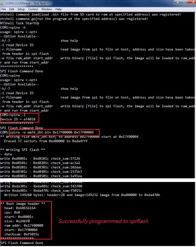
em7d_2bt.bininto spiflash - Run spirw to show help
- Run spirw -i to check SPI Flash ID, it should be Device ID = ef4018
- Run spirw -w em7d_2bt.bin 0x17f00000 0x17f00004 to program spiflash
- Check the output message to see if it has been programmed successfully
- Use ntshell command spirw to program the
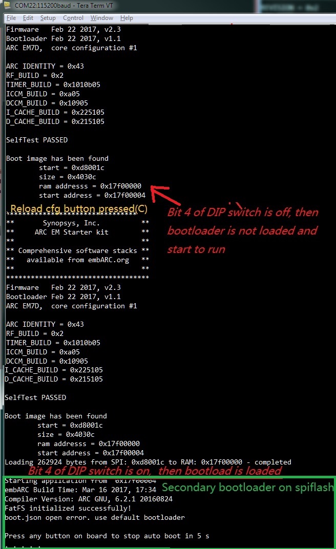
If programmed successfully, when the board is reset, make sure Bit 4 of the on-board DIP switch is ON to enable secondary bootloader run
If the SD card already contains the boot.bin in it, the bootloader automatically loads it from SD card. If not, it enters to ntshell mode
You can goto the next step to generate the
boot.binfor proper application you want to be auto-loaded in SD card
Generate
boot.binusing any embARC example, it’s RAM start address should be 0x10000000. Use bootloader to run it- Known Issues
- Boot rom of EMSK1.x is not able to load secondary bootloader on SPI Flash, you need a modified EMSK1.x mcs file to enable this function, send request in forum about this mcs file.
IoT Development Kit
- Generate a secondary bootloader binary file
- Program the secondary bootloader binary file into SPI Flash
- Insert SD card to your PC, and copy the binary file
obj_iotdk_10/mw_arcem9d/simple_bootloader_mw_arcem9d.binto SD card Root, and rename it tosimple_bootloader.bin - copy the file
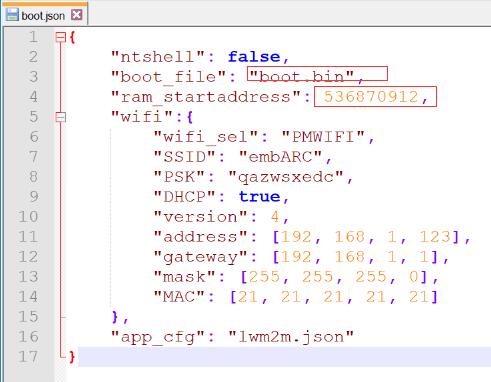
example/bootloader/boot.jsonto SD card root, and change the boot_file value toboot.bin, and change the ram_startaddress to 536870912(0x20000000)
- Insert the SD card to iotdk Board, rmove APPL_DEFINES += -DUSE_APPL_MEM_CONFIG in makefile, build and run the
<embARC>/example/baremetal/bootloaderexample, and enter to ntshell command mode.
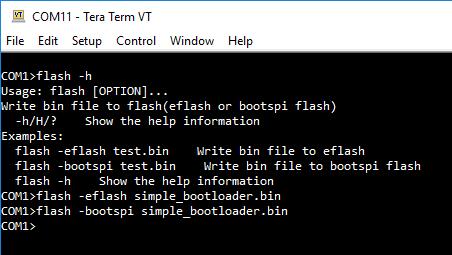
- Use ntshell command flash to program the
simple_bootloader.bininto both flash - Run flash -h to show help
- Run flash -eflsh simple_bootloader.bin to program eflash
- Run flash -bootspi simple_bootloader.bin to program bootspi flash
- Check the output message to see if it was programmed successfully
- Use ntshell command flash to program the
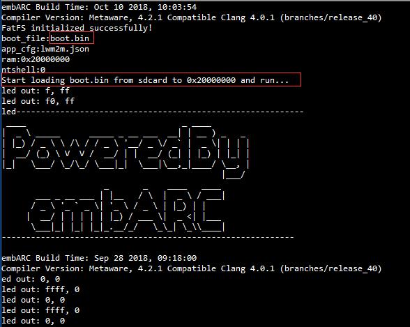
If the SD card already contains the
boot.binandboot.jsonin it, the bootloader automatically loads it from SD card, if not, it enters to ntshell modeYou can goto the next step to generate the
boot.binfor proper application you want to be auto-loaded in SD card
- Insert SD card to your PC, and copy the binary file
Generate
boot.binusing any embARC example, its RAM start address should be 0x20000000. Use bootloader to run it
Exercises
- Create and build a different self-boot embARC application
- Use the ntshell commands
- Use the UART-ymodem to load your application